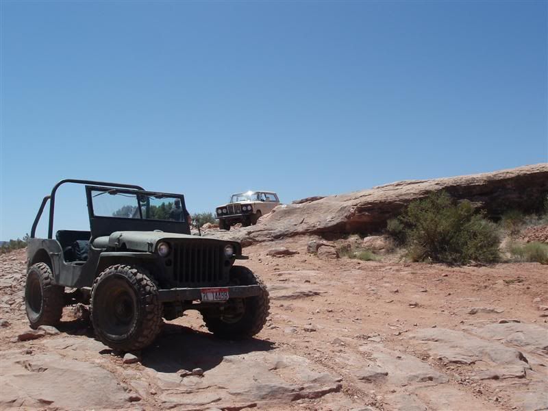
My old 1942 Willys has been in need of a refresh for a while now.....
![Image]()
This little guy is pushing 70 years old now so I figured it was time for a decent rebuild. Now, I don't want to hear any whining from the historical purists! This is a 1942 Willys MB, but it was never stock as long as I have owned it. I have tinkered with it for the last 8 years or so now. It is WAY too far gone to restore. Just like any much 'loved' jeep there is VERY little that is original. The specs as it sits currently are....
1942 Willys MB frame and body
1960s buick 225 v6 from a cj5 ( dual exhaust, HEI, holley 2bbl )
SM420 transmission ( 7.05:1 1st gear )
D18 t-case, twin stick, custom 1/2" long adapter to the transmission.
D44 rear axle from a cj5, 4.30 gears, powr-lok, 2pc axles
D25/27 front, 4.27 gears, disc brakes, crossover steering
Power steering conversion
hanging pedal conversion
70s GM column of some kind with a small steering wheel!
Overall its been a great little rig, but I have never fully trusted it. Its pushing 70 years now and I didn't do all the modifications. I found it in a field in Montana. The guy I bought it from got it from some guy who owed him money, who got it from the widow of the guy that did the major rebuid. That is how the story goes. I have tinkered with it for a few years now, but have always been on the fence about it. Its a cool piece of history, but its not worth restoring. Its been pretty much sitting around for over a year now. I finally hopped down off the fence and decided to rebuild it. I will be taking over the Rubicon late this summer/early fall........
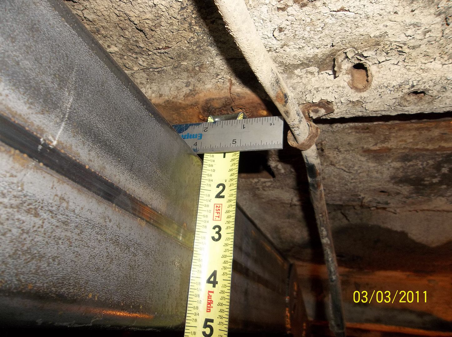
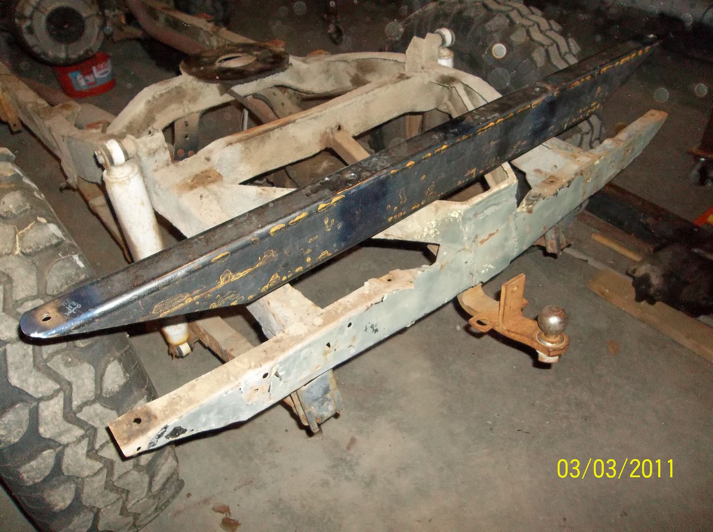
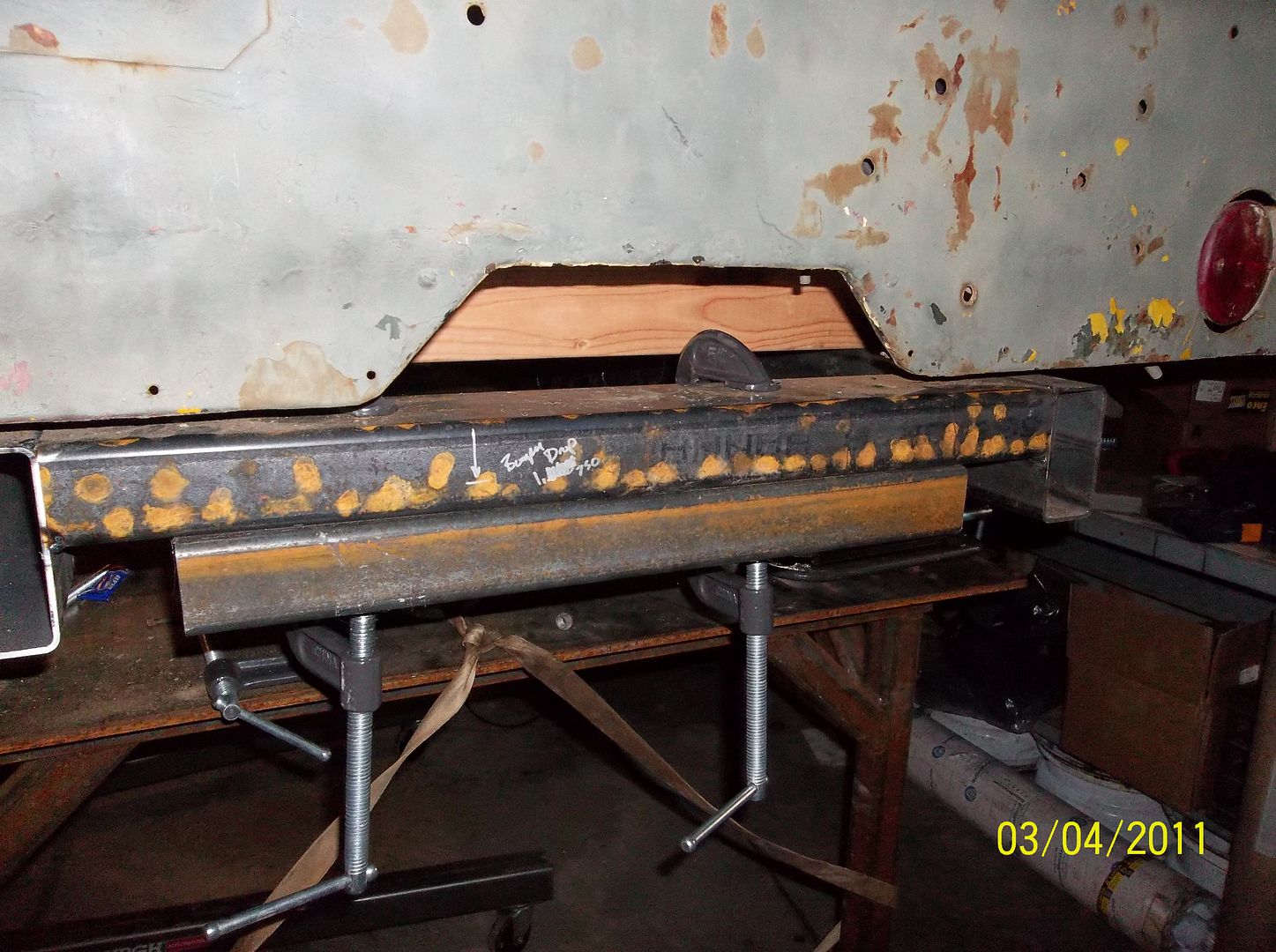
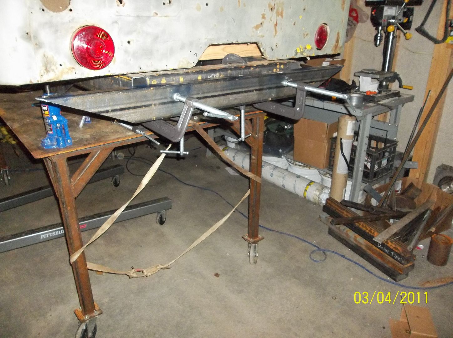
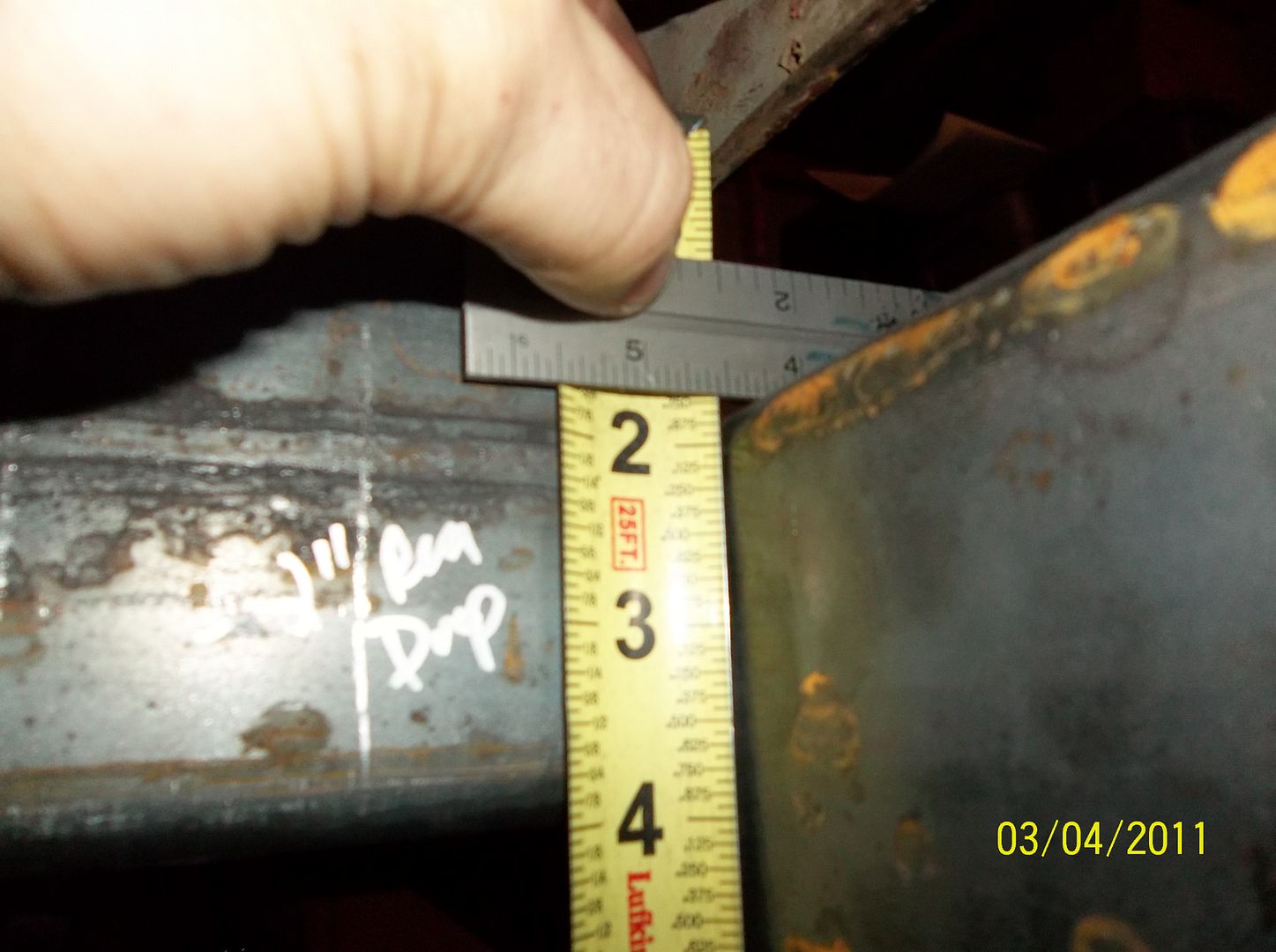
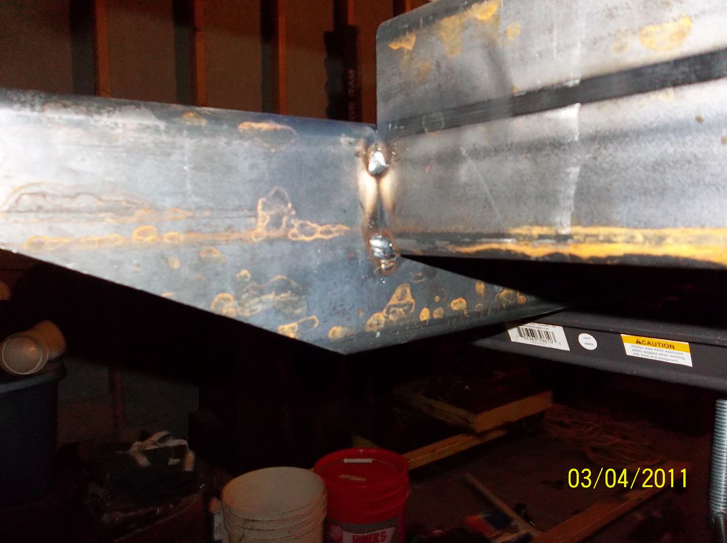
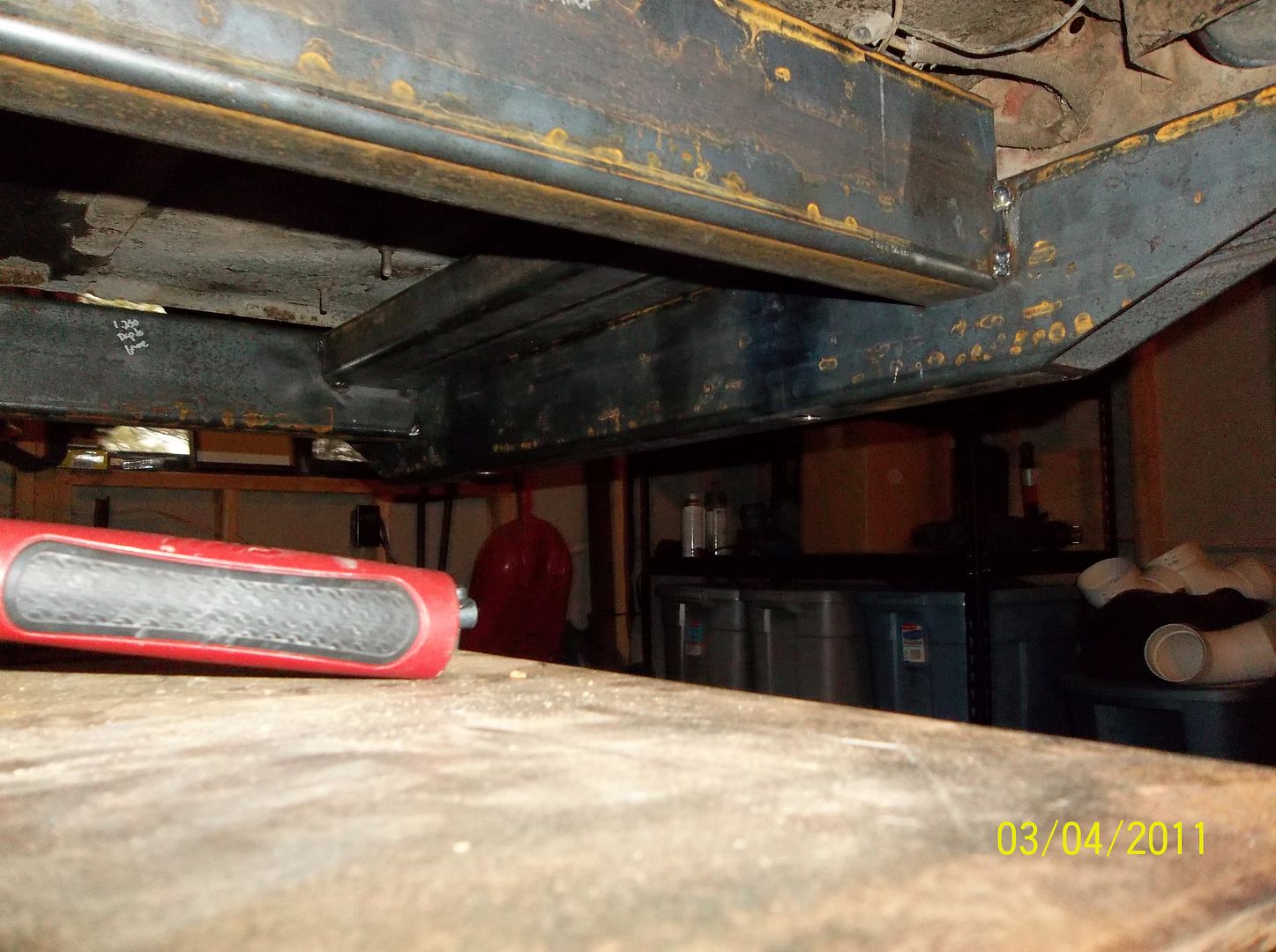
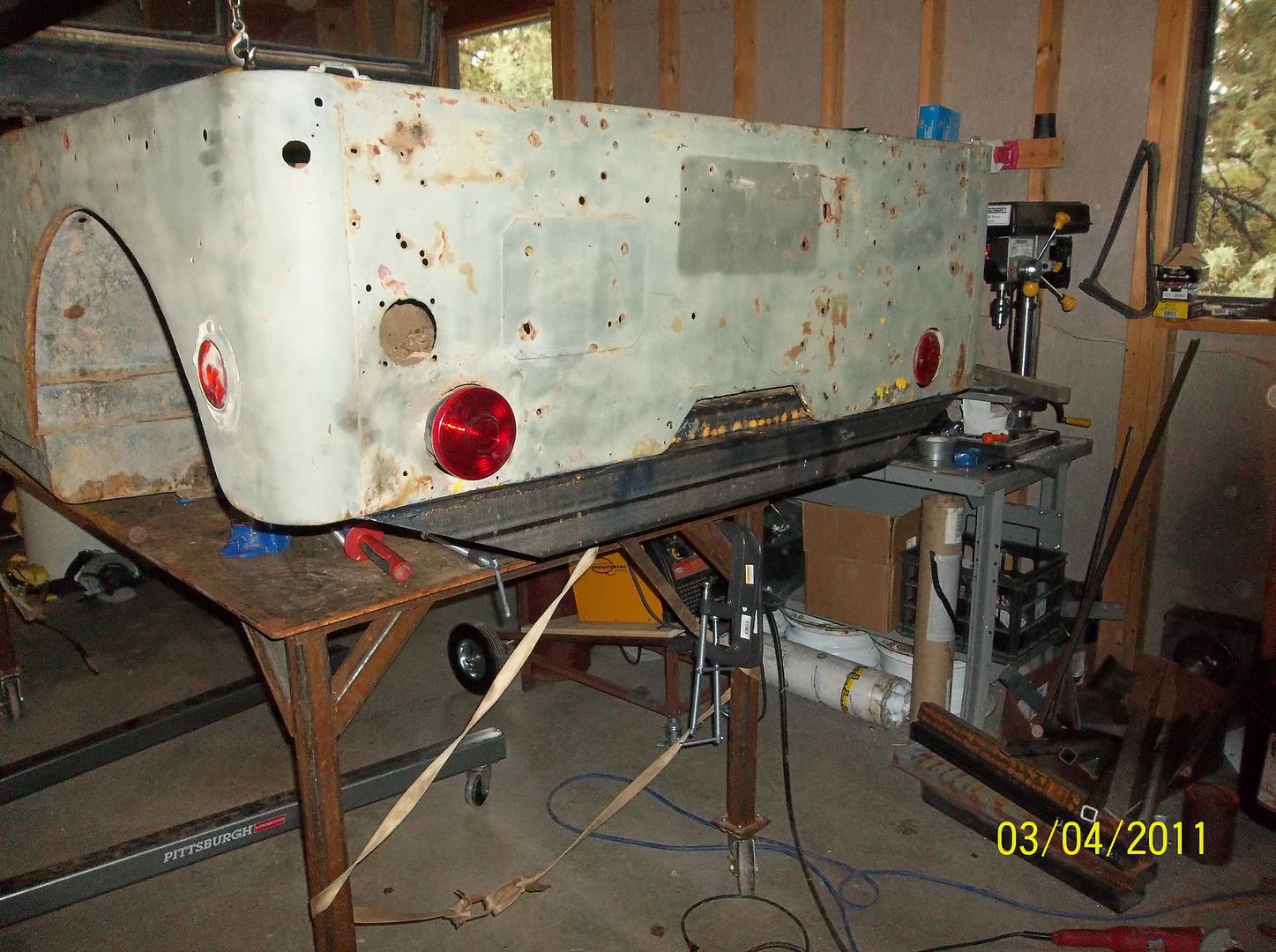
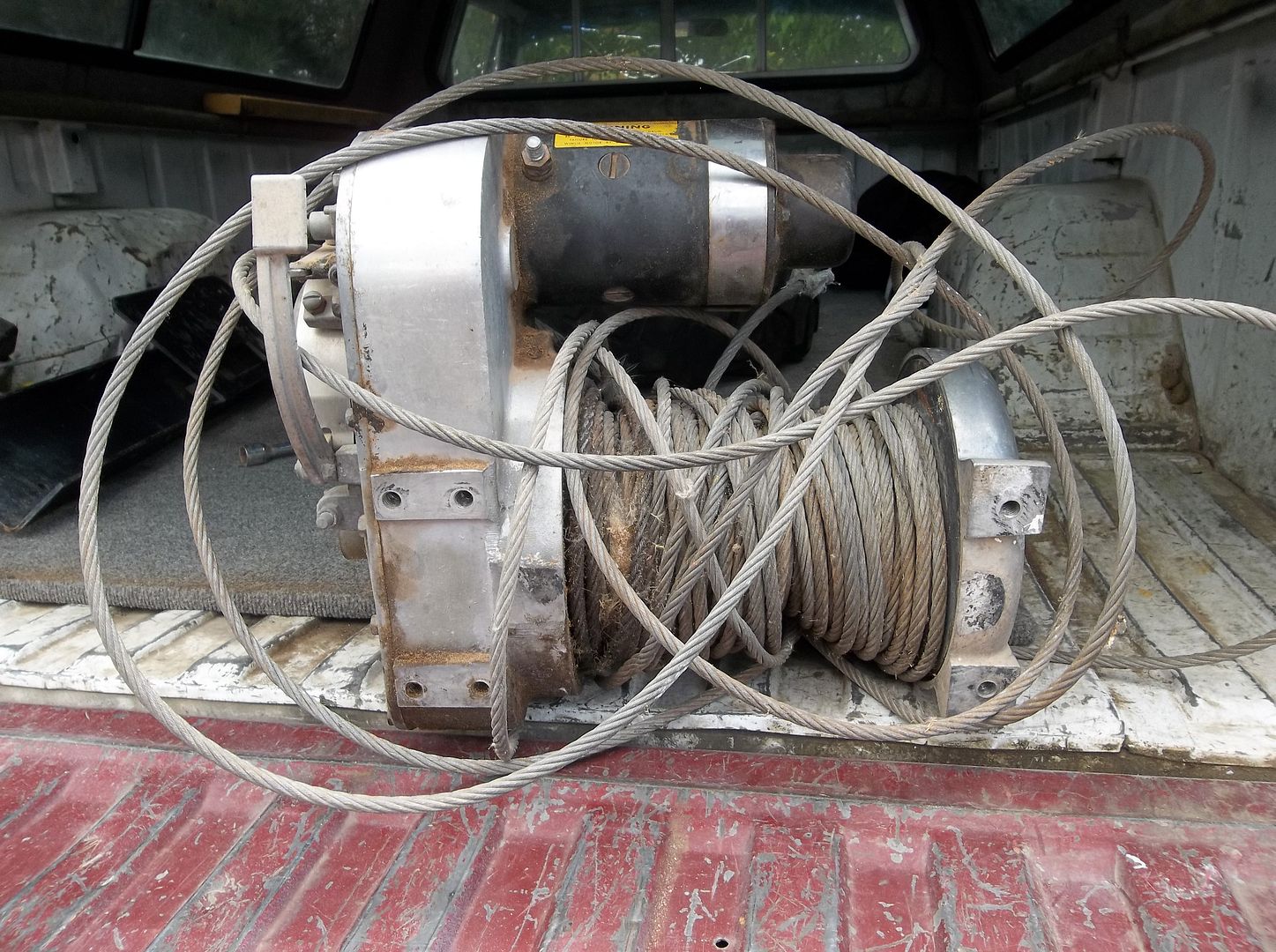
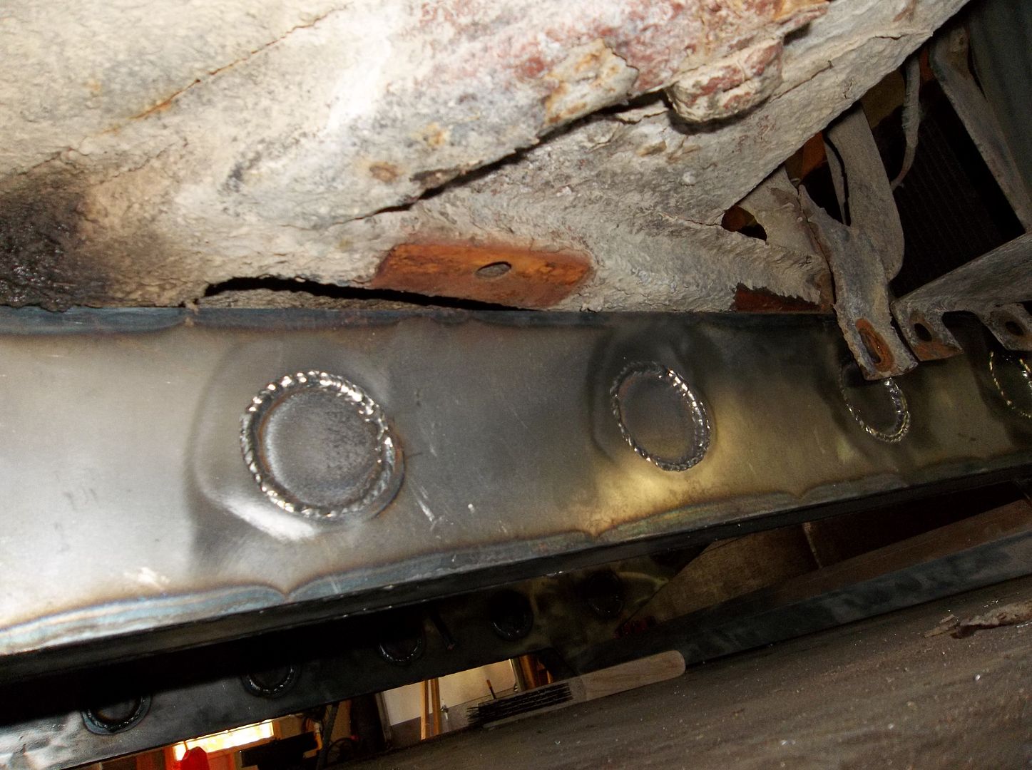
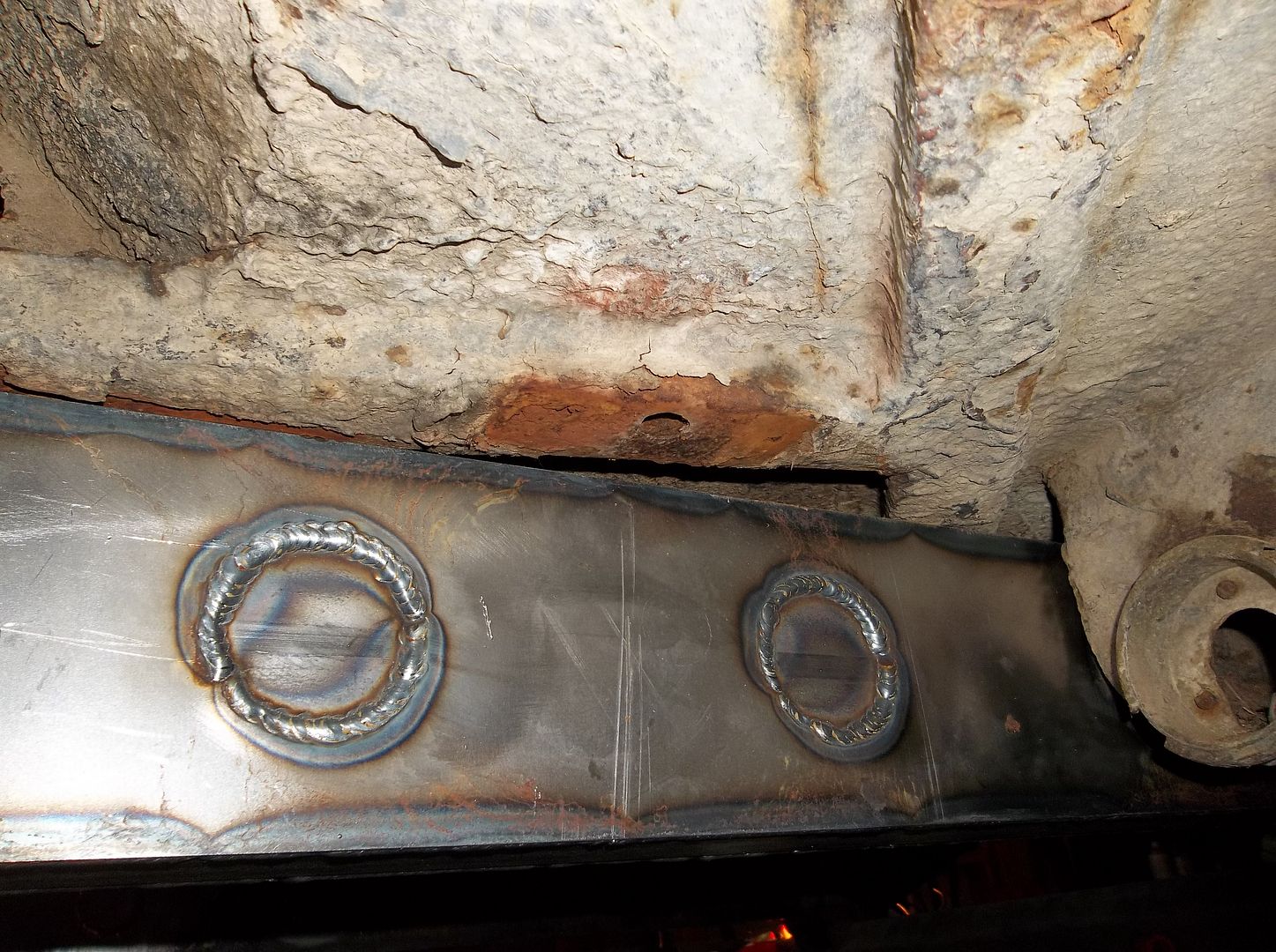
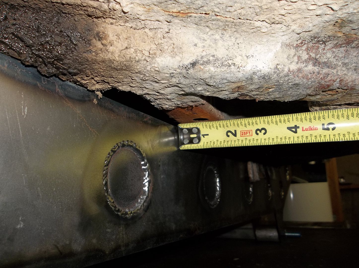
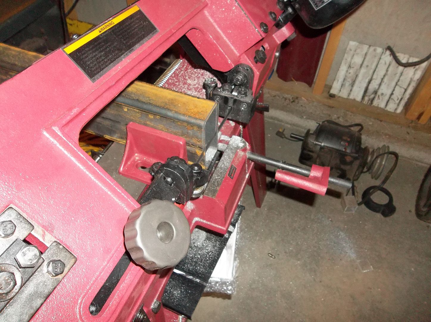
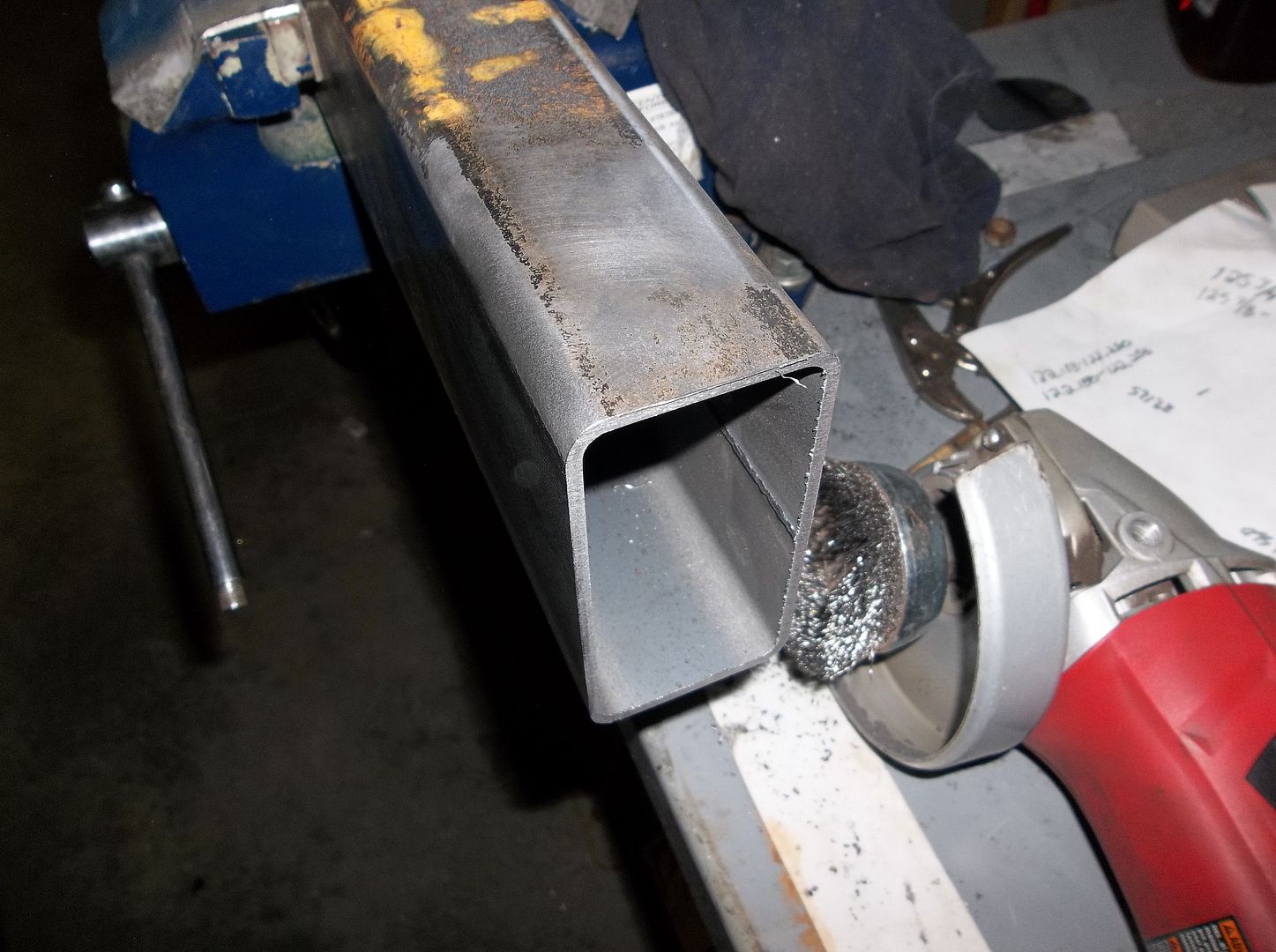
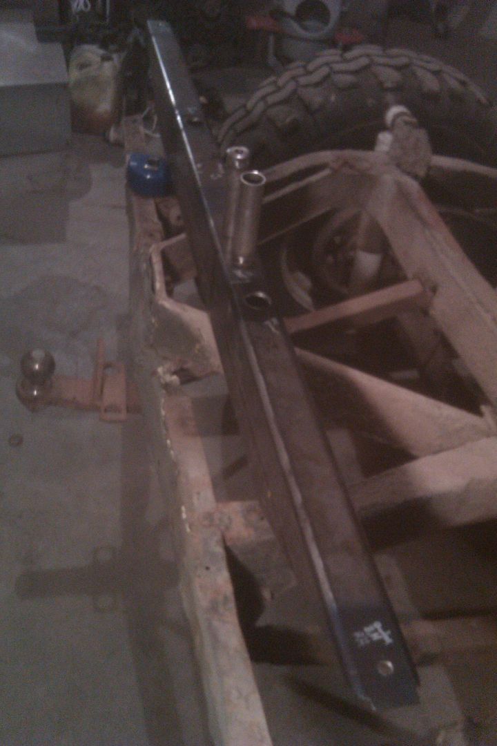
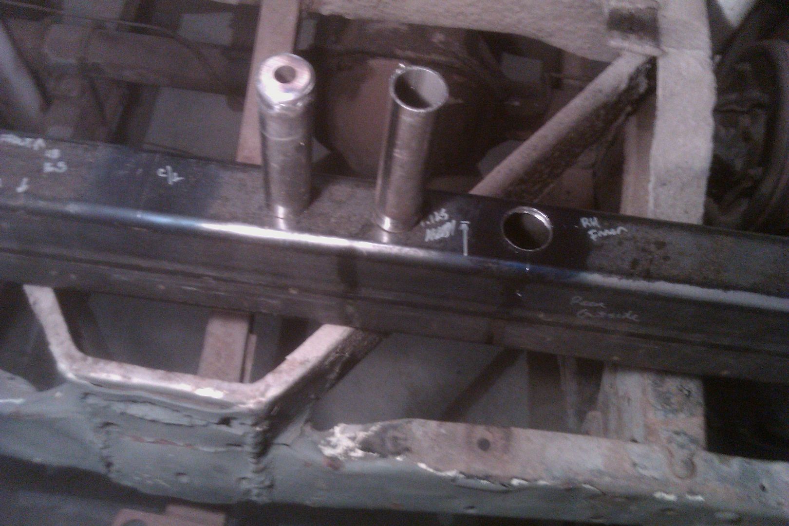
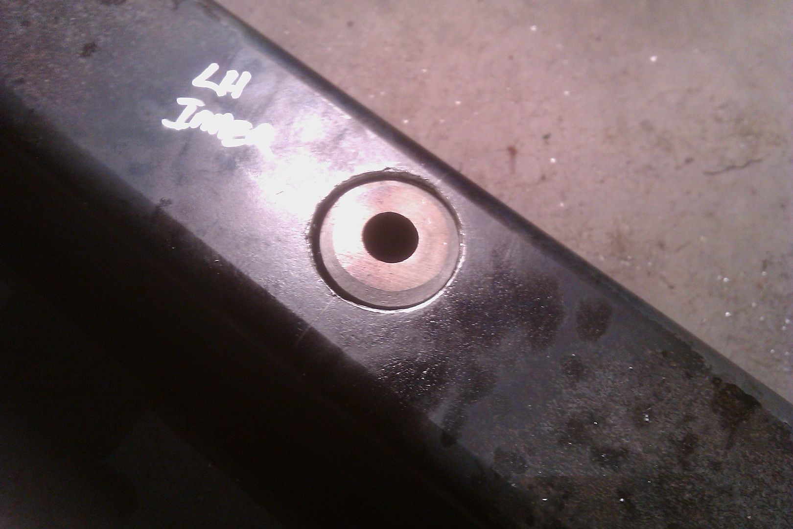
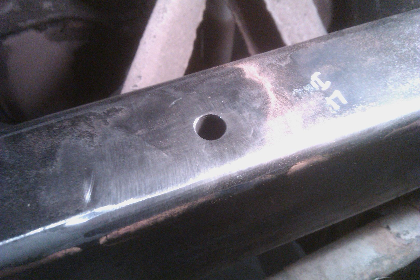
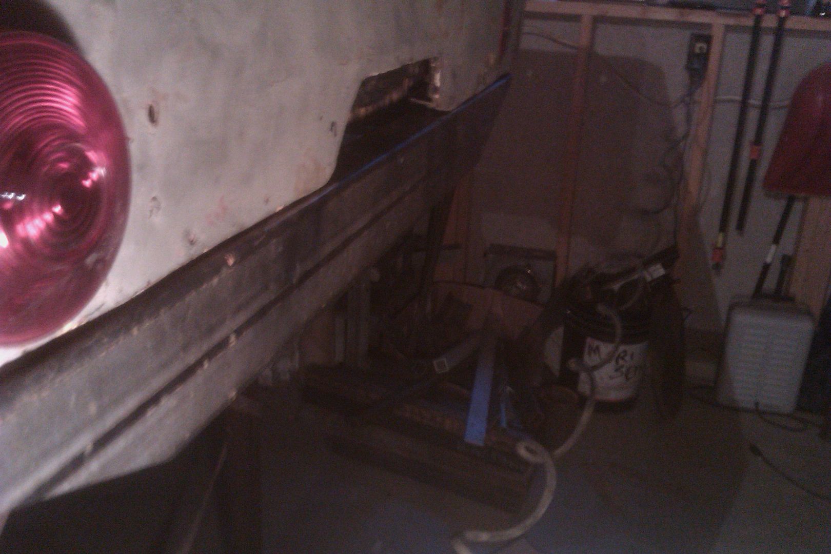
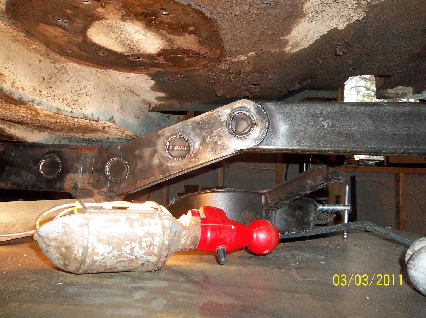
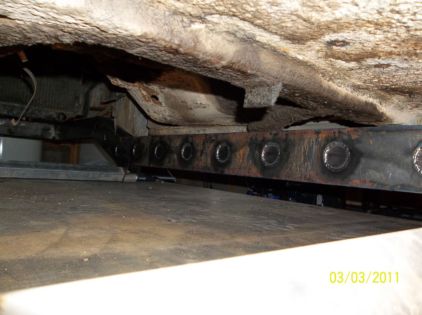
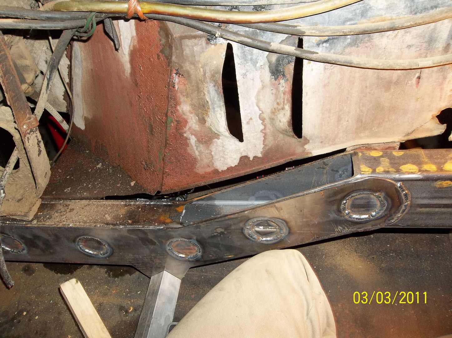
The biggest overall problem with this old guy is that the frame is HAMMERED! The rear K-member is trashed. It looked like someone was using it to pull a bulldozer out with it. Once of the front frame rails is a little bent around the steering box. There is also some rusting at the rear shackle mounts. I debated for a long time about what to do. You can get a new original frame for around $1500 or you can get a box frame for about $2000+. Like everything else lately....I decided to make my own.
After a few dozen hours with a tape measure, some old FSM type manuals, and a few hour on the computer I came up with a simple frame.....
![Image]()
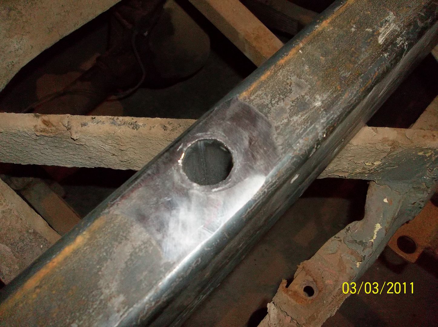
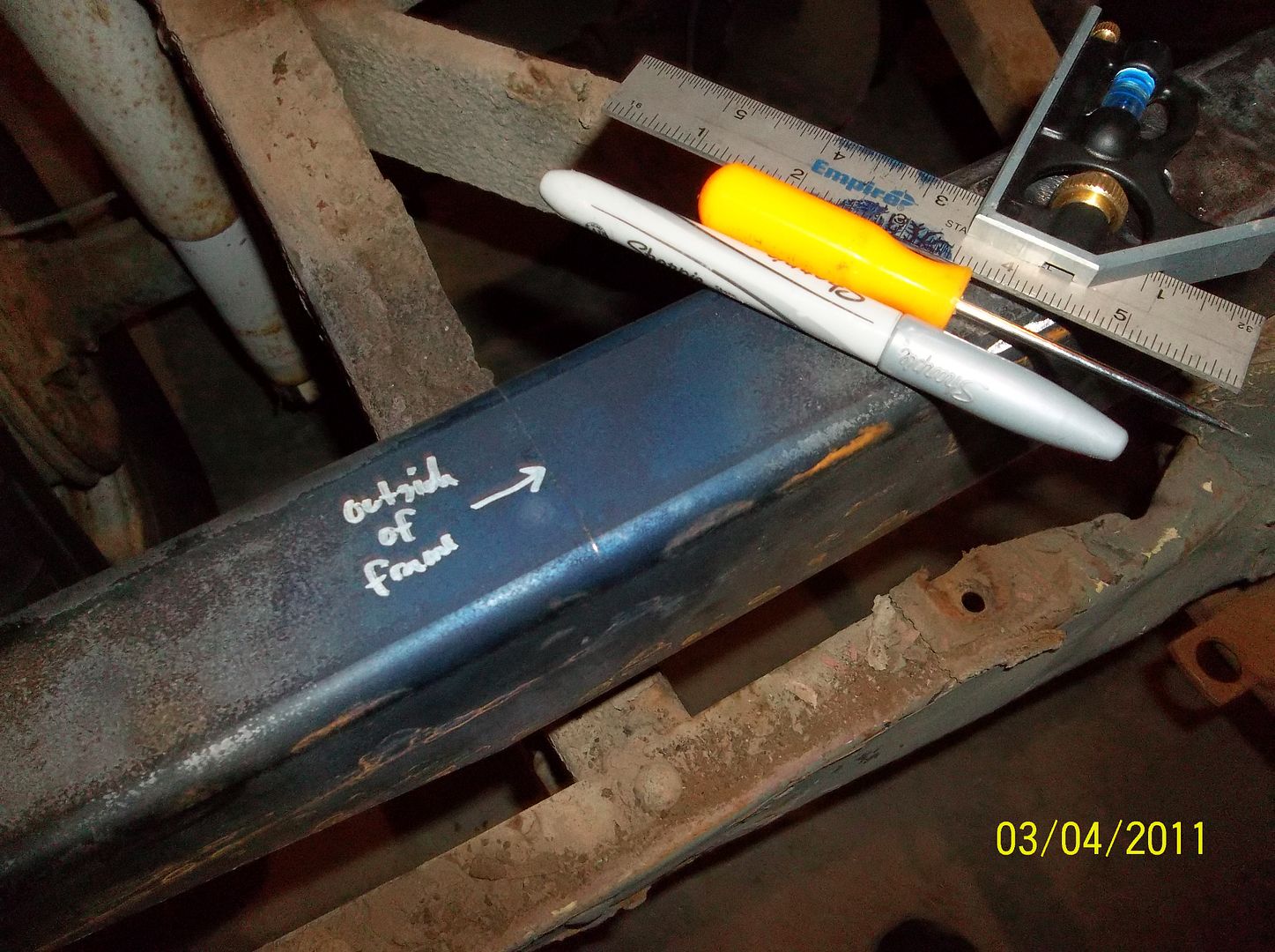
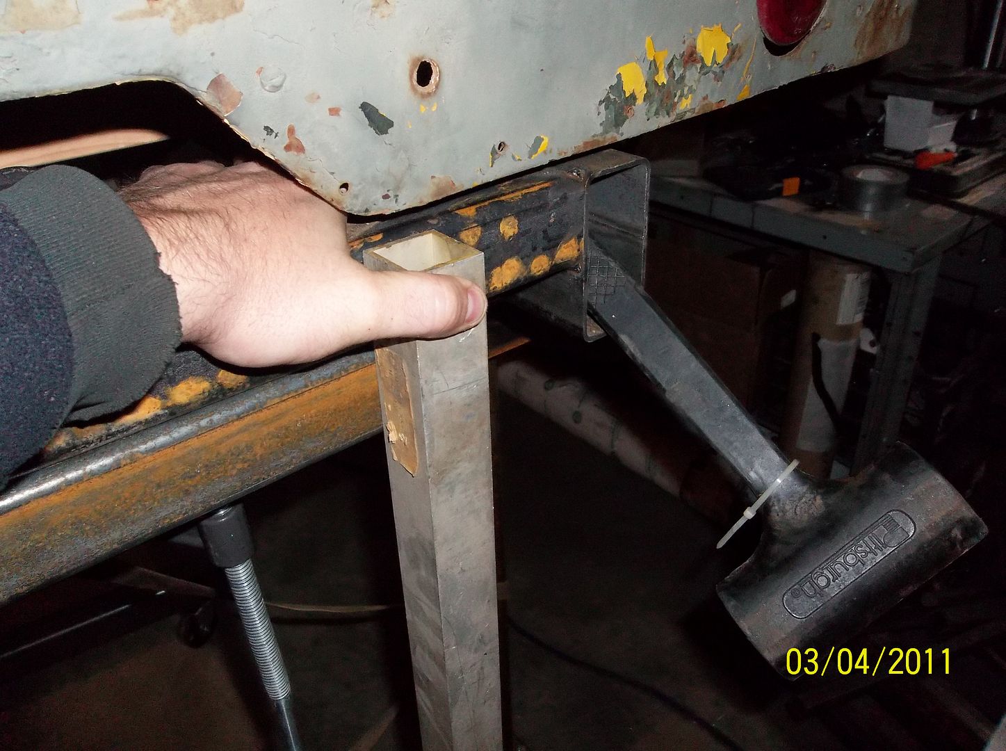
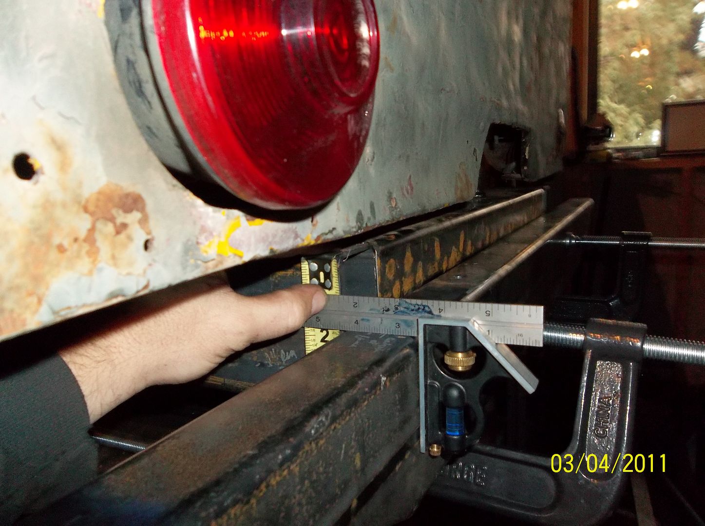
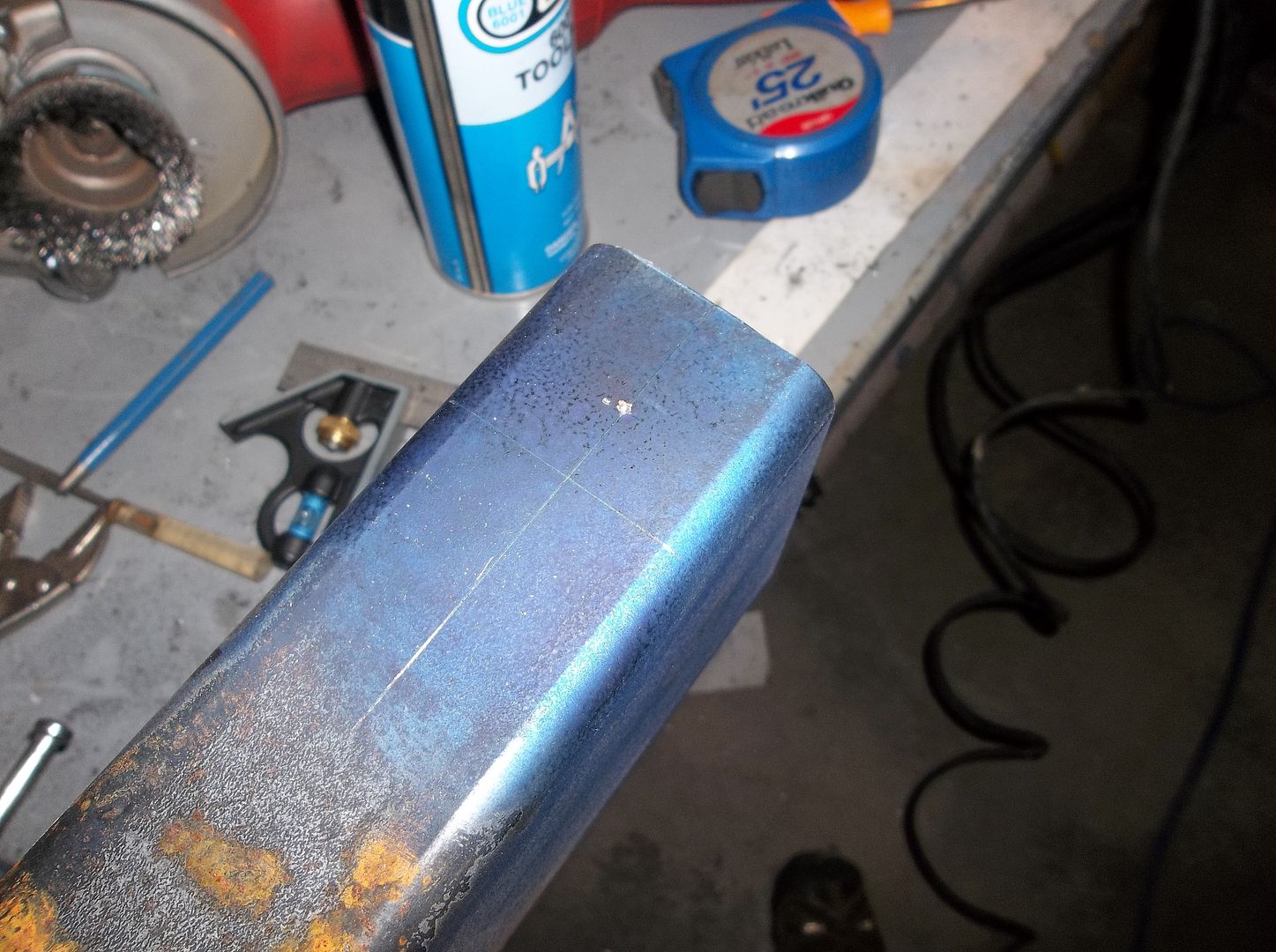
This rendering is not complete but shows the basic idea. The frame itself is constructed of 2x4 box tubing. The plates on the side define the critical measurements for the front and rear spring hangers. This will allow me to keep the frame very true when assembling it. I sent the side plates off to the laser cutter and ordered up two sticks of material. Total cost was less than $400 for everything shipped. The two sticks of material give me plenty for bumpers, cross members, and body mounts....
Update. ( I get a lot of requests for the frame print )
PDF of the frame is posted here...
http://www.expeditionportal.com/forum/threads/58343-Rango-1942-Willys-MB?p=1074445#post1074445
Still looking for a place to post the dxf/dwg for the side plates.
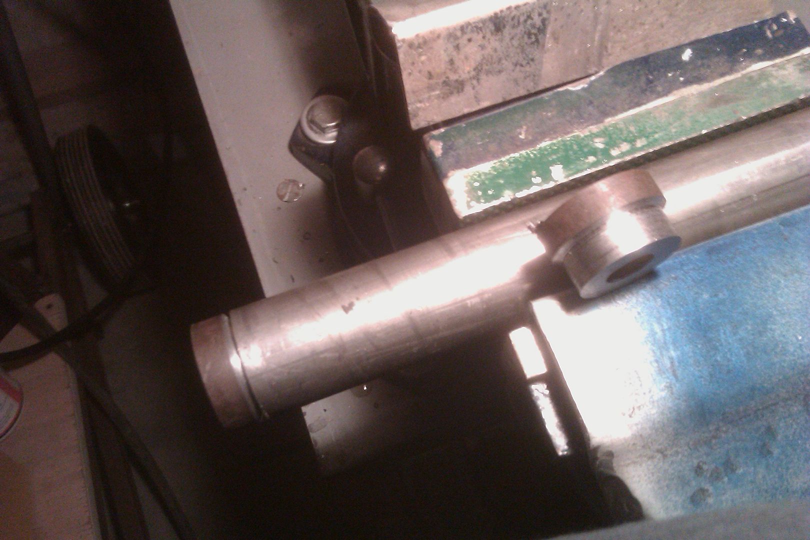
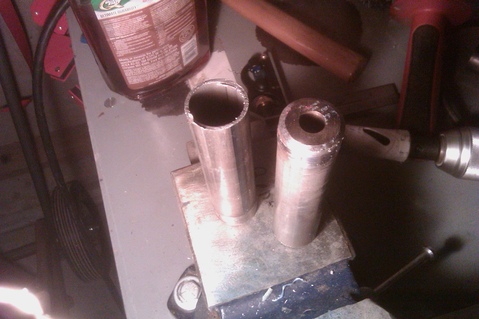
I had a member contact me about using the set of aluminum pucks I made to align the side plates and bolt the rails together when trimming the frame down.
Sadly I couldn't find the original set, I think I ended up turning them down into other things....
So...I made another set, this time out of some aluminum hex stock. This set will be traveling to the member who asked for them. The idea is when he is done he will either mail them back to me or onto the next person that needs them.
Thank you to hosting these files!
http://www.scotthansen.net/framemodel.pdf
http://www.scotthansen.net/frameplate.DXF
This little guy is pushing 70 years old now so I figured it was time for a decent rebuild. Now, I don't want to hear any whining from the historical purists! This is a 1942 Willys MB, but it was never stock as long as I have owned it. I have tinkered with it for the last 8 years or so now. It is WAY too far gone to restore. Just like any much 'loved' jeep there is VERY little that is original. The specs as it sits currently are....
1942 Willys MB frame and body
1960s buick 225 v6 from a cj5 ( dual exhaust, HEI, holley 2bbl )
SM420 transmission ( 7.05:1 1st gear )
D18 t-case, twin stick, custom 1/2" long adapter to the transmission.
D44 rear axle from a cj5, 4.30 gears, powr-lok, 2pc axles
D25/27 front, 4.27 gears, disc brakes, crossover steering
Power steering conversion
hanging pedal conversion
70s GM column of some kind with a small steering wheel!
Overall its been a great little rig, but I have never fully trusted it. Its pushing 70 years now and I didn't do all the modifications. I found it in a field in Montana. The guy I bought it from got it from some guy who owed him money, who got it from the widow of the guy that did the major rebuid. That is how the story goes. I have tinkered with it for a few years now, but have always been on the fence about it. Its a cool piece of history, but its not worth restoring. Its been pretty much sitting around for over a year now. I finally hopped down off the fence and decided to rebuild it. I will be taking over the Rubicon late this summer/early fall........
The biggest overall problem with this old guy is that the frame is HAMMERED! The rear K-member is trashed. It looked like someone was using it to pull a bulldozer out with it. Once of the front frame rails is a little bent around the steering box. There is also some rusting at the rear shackle mounts. I debated for a long time about what to do. You can get a new original frame for around $1500 or you can get a box frame for about $2000+. Like everything else lately....I decided to make my own.
After a few dozen hours with a tape measure, some old FSM type manuals, and a few hour on the computer I came up with a simple frame.....
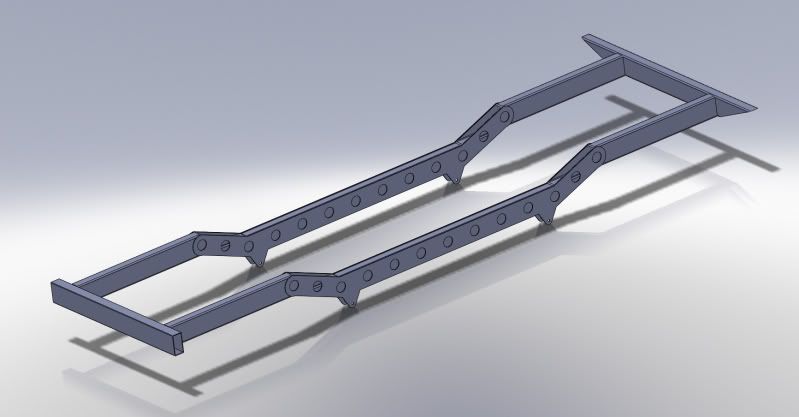
This rendering is not complete but shows the basic idea. The frame itself is constructed of 2x4 box tubing. The plates on the side define the critical measurements for the front and rear spring hangers. This will allow me to keep the frame very true when assembling it. I sent the side plates off to the laser cutter and ordered up two sticks of material. Total cost was less than $400 for everything shipped. The two sticks of material give me plenty for bumpers, cross members, and body mounts....
Update. ( I get a lot of requests for the frame print )
PDF of the frame is posted here...
http://www.expeditionportal.com/forum/threads/58343-Rango-1942-Willys-MB?p=1074445#post1074445
Still looking for a place to post the dxf/dwg for the side plates.
I had a member contact me about using the set of aluminum pucks I made to align the side plates and bolt the rails together when trimming the frame down.
Sadly I couldn't find the original set, I think I ended up turning them down into other things....
So...I made another set, this time out of some aluminum hex stock. This set will be traveling to the member who asked for them. The idea is when he is done he will either mail them back to me or onto the next person that needs them.
Thank you to hosting these files!
http://www.scotthansen.net/framemodel.pdf
http://www.scotthansen.net/frameplate.DXF
")