Project: Scoutzall r2.2
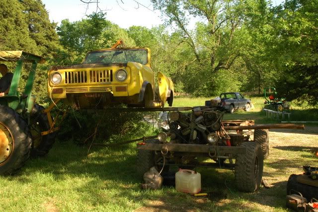
Subect: 1974 RHD Scout II
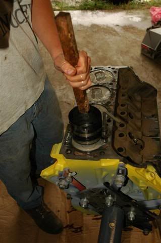
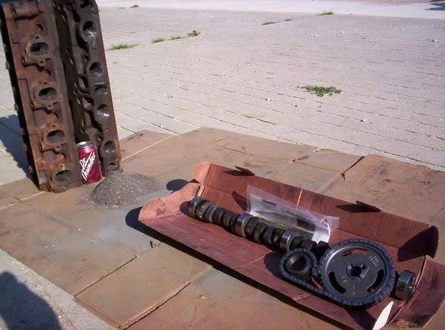
Drivetrain: 460-ZF-1356-np205
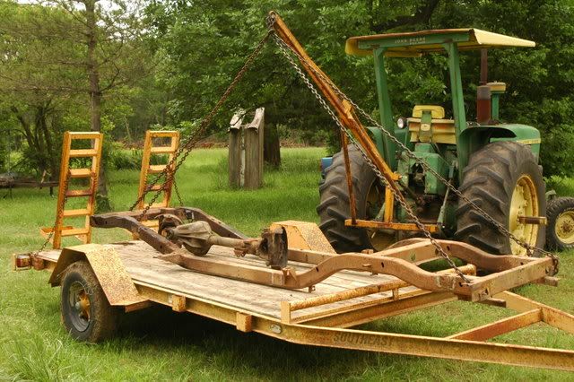
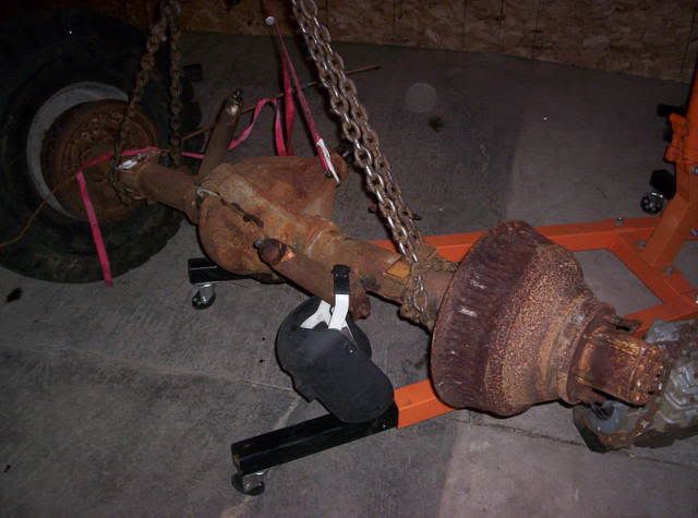
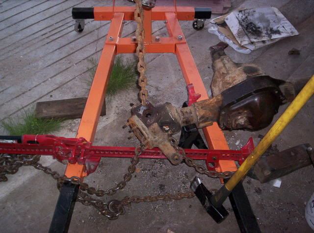
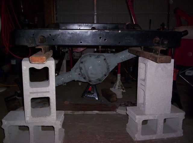
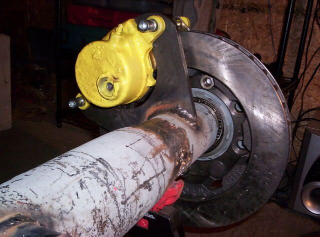
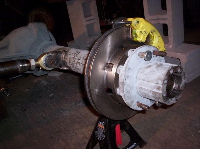
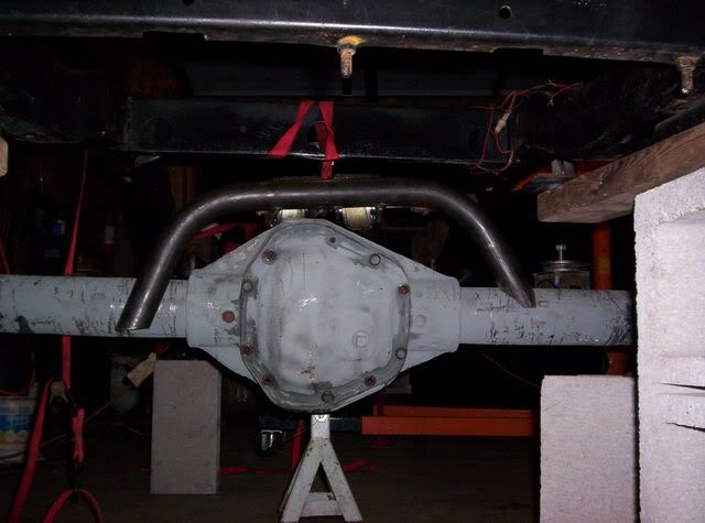
Axles: Dana 60/Dana 70 dually's 4Xdisks
Tires: 40"+ on H1's
Winch: Warn M12000
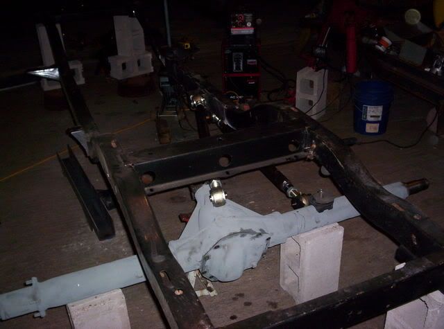
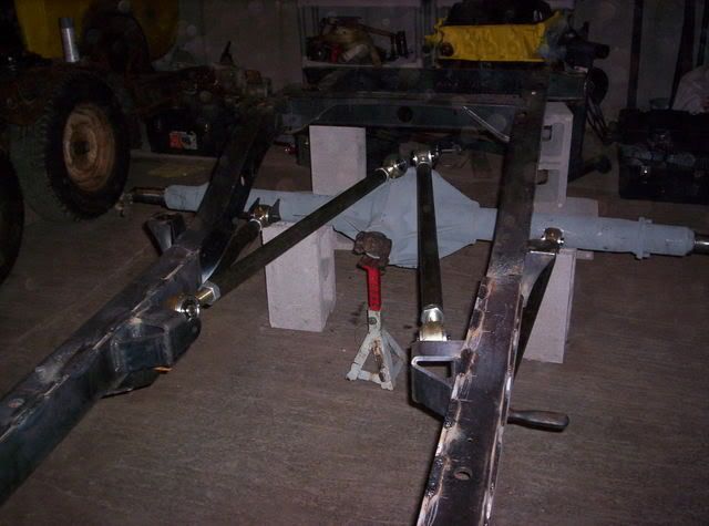
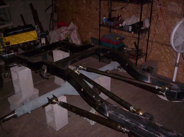
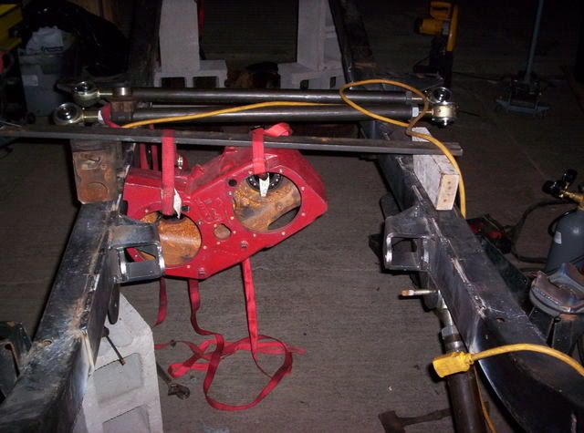
Suspension: Prototype D&C 4-link w/SAW coil-over front and standard coil rear kit.
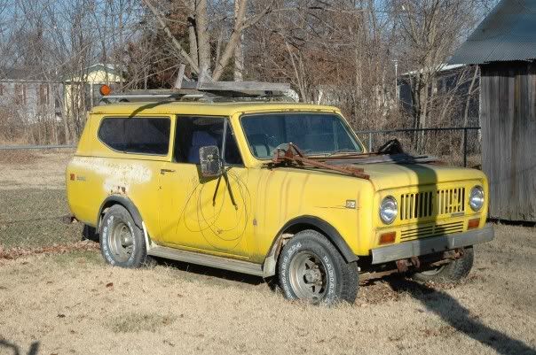
Scout r2.0
![Image]()
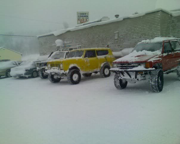
Scout r2.1
![Image]()
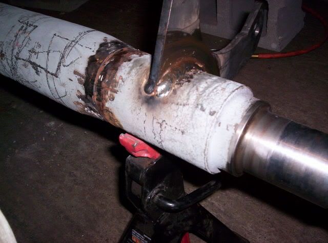
This build will be done as quickly and thoroughly as possible to see if this new kit from D&C will take as much time and guesswork out of 4-linking as it appears it will. However I absolutely will not compromise quality for build speed, so if it takes longer so be it. Unlike my previous start at a build thread, I now have a steady, good paying job as a co-op mechanical engineer at mercury marine and a decent indoor shop setup with good tools. I should be putting the money toward the last semesters of college at MTU commencing in January, but lets just call this an "investment".
-Kansas 4x4 service
Subect: 1974 RHD Scout II
Drivetrain: 460-ZF-1356-np205
Axles: Dana 60/Dana 70 dually's 4Xdisks
Tires: 40"+ on H1's
Winch: Warn M12000
Suspension: Prototype D&C 4-link w/SAW coil-over front and standard coil rear kit.
Scout r2.0
Scout r2.1
This build will be done as quickly and thoroughly as possible to see if this new kit from D&C will take as much time and guesswork out of 4-linking as it appears it will. However I absolutely will not compromise quality for build speed, so if it takes longer so be it. Unlike my previous start at a build thread, I now have a steady, good paying job as a co-op mechanical engineer at mercury marine and a decent indoor shop setup with good tools. I should be putting the money toward the last semesters of college at MTU commencing in January, but lets just call this an "investment".
-Kansas 4x4 service